A multimeter can also be expertly used for continuity testing. Many digital multimeters boast of a continuity test mode which allows you to test and examine fuses switches electrical connections and conductors etc.
How To Use A Multimeter On Audio Equipment Coolcircuit Com
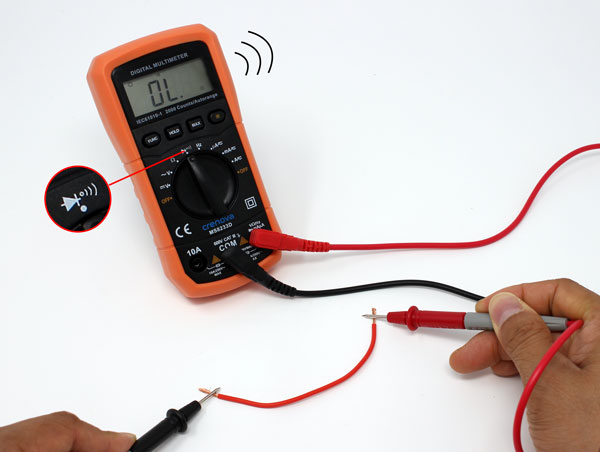
Certain multimeters have a continuity check causing a loud beep if 2 points are electrically attached.
Muli meter continuity between two points. Ask Question Asked 1 year 11 months ago. The meter will emit an audible tone when continuity is detected between two points. If there is very low resistance between two points which is less than a few ohms the two points are electrically connected and youll hear a continuous sound.
How do I test a component for continuity. Book - Chapter 3. This feature allows us to test for conductivity of materials and to trace where electrical connections have been made or not made.
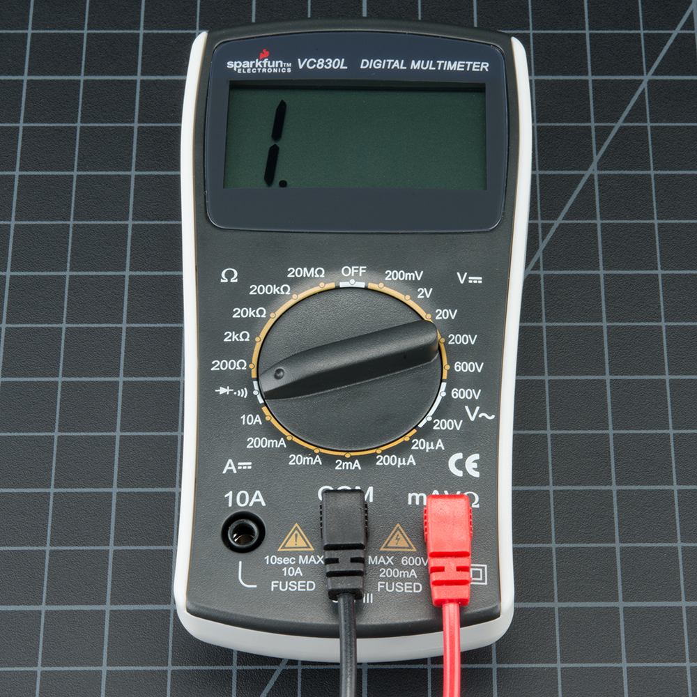
When checking for continuity between two points on a PCB how do I know its not going through an inductor. Turn the dial to Continuity Test mode. Continuity test with a multimeter.
This is 200 ohms on many multimeters. In the simplest of terms continuity testing is the act of testing the resistance between two points. The multimeter is looking for very low resistance to see if two points are connected.
Capacitors will act like a short for a split second until they fill up with energy and then act like an open connection. A continuity tester is an item of electrical test equipment used to determine if an electrical path can be established between two points. Procedure 1 Continuity Check 5 points Use your multimeter to verify the connections in your breadboard in the first 5 columns and the top two rows of the breadboard as indicated on the diagram below Figure P1-1.
Checking for continuity is an easy way to see if 2 ends of something ar. First insert the black test lead into the COM jack. This can be helpful when tracing broken wires or assuring that a solid connection.
Only a closed complete circuit one that is switched ON has continuity. In this episode of Repair and Replace Vance shows how to do continuity test with a multimeter. This mode is also called as diode mode buzzer mode.
In this activity you will be using the multimeter to do a continuity test on the breadboard by touching the probes to some wire and then to some plastic. Continuity is non-directional you can switch probes and it will be the same. If you are testing two points in a circuit and there is a big capacitor between those points you may hear a quick beep and then quiet.
With the test probes separated the multimeters display may show OL and Ω. The circuit under test is completely de-energized prior to connecting the apparatus. How does continuity mode work in multimeter.
During a continuity test a digital multimeter sends a small current through the circuit to measure resistance in the circuit. This is a fast and effective way for finding short circuits or open circuits. The beep indicates everything is linked as well as nothing has come loose.
A meter with a continuity beeper briefly sounds off when it detects a closed circuit. This test helps insure that connections are made correctly between two points. If required press the continuity button.
Multimeter continuity no beep. Analog inductor components multimeter reverse-engineering. Then insert the red lead into the VΩ jack.
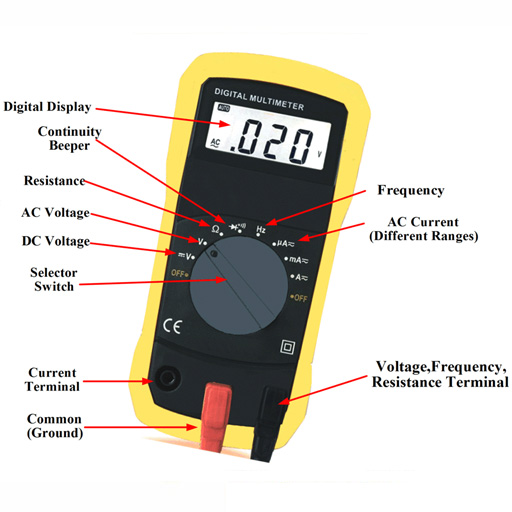
A multimeter is a devise used to measure voltage resistance and current in electronics electrical equipment It is also used to test continuity between to 2 points to verify if there is any breaks in circuit or line There are two types of multimeter Analog Digital Analog has a needle style gauge Digital has a LCD display Referenced during this PPT There are 2 styles of multimeters Switched Auto Range Manually switch Switches between between. That is if an electrical circuit can be made. Lets assume I have access to a basic multimeter power supply oscilloscope and function generator.
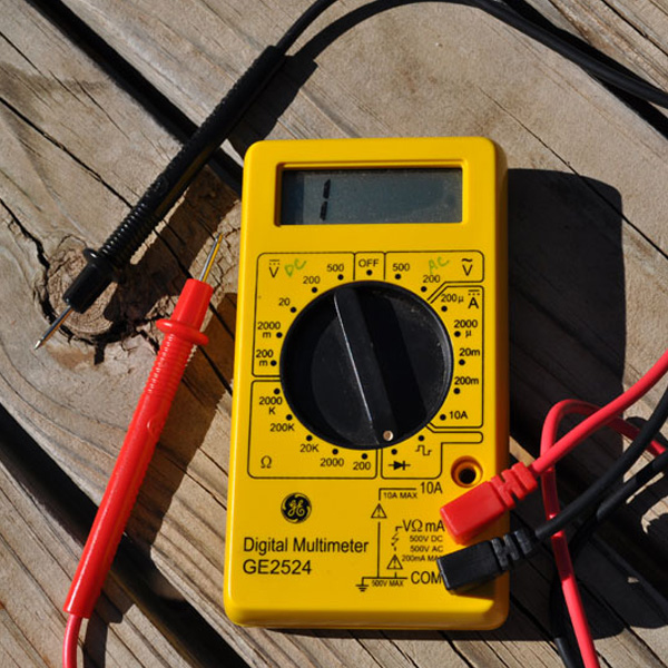
This is a quick video of me showing you how to test for continuity with a multimeter. It will likely share a spot on the dial with one or more functions usually resistance Ω. Simply place one probe on one point and another probe on another point and and your meter will give you a visual and audible signal.
That usually means both probes must be grasped by the users hands and held against the proper contact points of a voltage source or circuit while measuring. Put your multimeter on the lowest setting of Ohms Ω possible. This is because there is often significant amounts of capacitance on the power system.
Continuity is also measured in ohms so youll use the same V port you used for resistance but in testing continuity youre more likely testing whether two points are connected at all. This is useful if for circumstances you are developing a circuit and connecting cables or soldering. This test also helps us detect if two points are connected that should not be.
This preview shows page 5 - 7 out of 12 pages. - Figure P1-1 - Partial breadboard Set your multimeter on resistance. Being that voltage is always relative between two points the meter must be firmly connected to two points in a circuit before it will provide a reliable measurement.
Continuity is quite possibly the single most important function for embedded hardware gurus. Thats because the voltage the meter is applying to the circuit is charging up the capacitor and during that time the meter thinks.
How To Use A Multimeter Learn Sparkfun Com

How To Use Multimeter To Test Your Drone Oscar Liang
Cs Stem Network
How To Use A Digital Multimeter To Test Continuity Coolcircuit Com

How To Use Multimeters
